Using Designer
The Zircon3D Designer is the workspace where you build, edit, and configure your entire 3D home or building model. It provides the tools needed to design your floorplan, place objects, and link real-world sensor data to create meaningful visualizations.
With the Designer you can:
- Create and edit your Home Plan, including buildings, floors, rooms, walls, openings, and structural elements.
- Place objects such as furniture, lights, sensors, and appliances, and organize them within your space.
- Draw connections between equipment using Edit Routing.
- Bind monitored devices, entities, and data points from Home Assistant to enable rich, real-time Data Visualization.
- Configure Heatmap Layers, Dashboards, and View Profiles to create customized monitoring views for daily use.
Use Designer Mode to build your environment, configure data, and prepare the views that will later be explored in the Viewer.
Designer Mode UI Overview
The Designer UI consists of several functional zones:
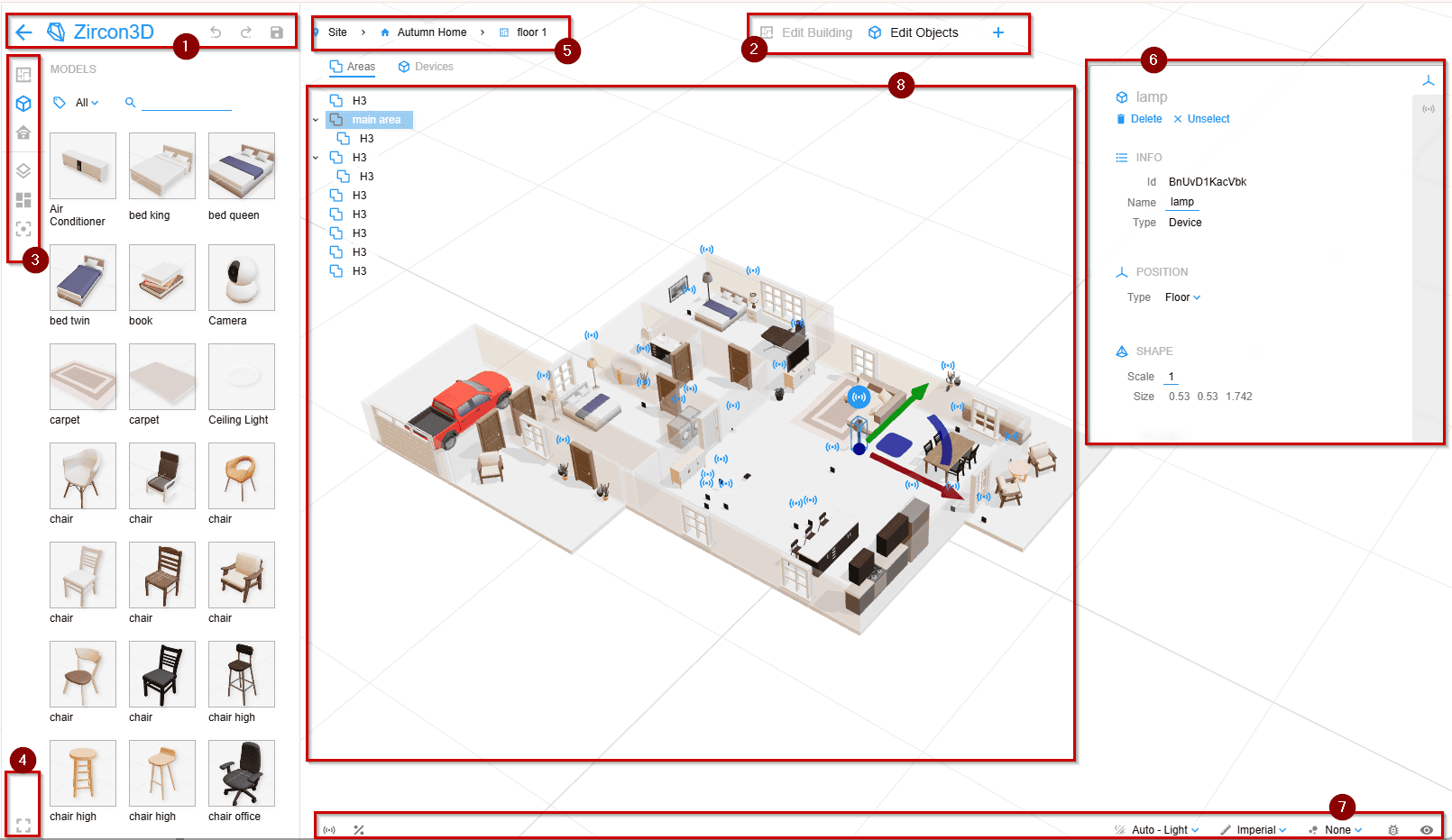
-
Title Bar
Shows the application title and the current project name, and providesUndo,Redo, andSaveactions for the current project. -
Editor Bar
Switches betweenEdit Building,Edit Objects,Edit Routing, andPreview, and allows you to add new buildings or floors. The Designer automatically switches between edit modes based on your selection. -
Left Side Panels
Switch among side panels:Building Parts,Objects,Monitoring,Layers,Dashboards, andView Profiles. ChooseObjectsto open the Models panel, where you can browse models, import custom models, and add adjustable Cubes or PV Arrays. -
Quick Access Buttons
Togglefull screen, and hide the entireUI layer. -
Breadcrumb Navigation Bar
Changes thescopeof the home plan, for example, to show only a specificfloor. -
Property Panel
Shows the properties of the currently selected location, including rooms, floors, objects, or sensors. -
Status Bar
Provides quick access to designer settings, includingconnection status,quota status,heatmap topic,heatmap replay timeline,view settingsandcamera controlfor touch devices (tablets and phones).. -
Center 3D Workspace
Where you draw rooms, move walls, place objects, and view your floorplan.
Camera Control
The camera determines how you view the 3D scene. You can pan, rotate, and zoom to inspect your layout from any angle.
Mouse controls
-
Panning — Hold the right mouse button and move the mouse.
-
Rotating — Hold the left mouse button and move the mouse.
-
Zooming — Use the mouse wheel to zoom in and out.
Touch controls
- Rotating / Tilting — Drag with one finger to rotate the floorplan or move the view up and down.
- Zooming — Pinch with two fingers to zoom in and out.
- Panning — Move two fingers in the same direction to move the view.
Note
On phones and tablets, you can also use the on-screen camera control buttons from the bottom bar to pan, rotate, and zoom the scene.
Change Scope
Scope defines how much of the project is visible at once.
By default, the scope is Site, which displays all buildings and floors.
Using the Breadcrumb Navigation Bar, you can adjust the scope to focus on:
- Site — Show all buildings in the project.
- Building — Show one building
- Floor — Show one specific floor
This helps reduce clutter and simplifies editing.
Selection & Edit Modes
Zircon3D provides three editing modes:
-
Edit Building Edit building structure such as rooms, walls, windows, doors, and openings.
Objects cannot be selected in this mode. -
Edit Objects Edit furniture, lights, sensors, appliances, cameras, and other objects.
Building parts cannot be selected in this mode. -
Edit Routing Draw and adjust connections between equipment ports. See Editing Routing for preparing objects, drawing paths, and connecting equipment across floors.
Note
The Designer automatically switches between editing modes based on the element you select.